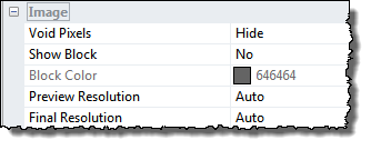
The Image section of the View Settings Pane defines how the image is drawn
Void pixels can be shown or hidden, which means that they are transparent.
To give the surface the appearance as if it was cut out of a block you can turn show block on.
During interactive rotation and scaling of the image it is often necessary to lower the "preview resolution" in order get a feeling of real-time updates, this is by default done automatically. Likewise, it might be desirable to lower the "Final Resolution" which is applied after when the interactive modification of the 3D scene has finished.
By the altering the resolution parameters you have the possibility to define how much you want to lower the resolution and adapt it to the performance of your computer.
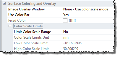
It is possible to attribute a single color to the surface or let the colors depend on the height values of the image or some other image of same size.
This parameter determines if the colors should be based on another 2D image open in SPIP or based the image itself.
When Image Overlay Window is set to None the surface color property is determined by the height values of the image. Combined with light sources it can create the illusion of a surface consisting of different materials. The height values will by default be scaled linearly between the min and max height values range of the image. When using a color scale with low contrast the best results are usually obtained.
Sometimes it can be useful to combine the topographic information from one image with colors from another image expressing some other surface properties, for example you can overlay an AFM height image with colors from its phase image (when acquired simultaneously).

3D Overlay example: Top left is a height image and top right a phase image recorded simultaneously using an AFM in tapping mode. Bottom left shows a 3D visualization of the height image with the original color coding (the corners of the original image have been defined as void pixels and are invisible) At bottom right is shown the 3D visualization of the height image with the color contrast from the phase image overlaid.
Data courtesy Günter Helas, Dr., Max Planck Institute for Chemistry, Biogeochemistry Department
Fixed Color
When Mode is set to Material the surface color can be defined by a fixed color.
Note, that the observed colors are determined by the light sources in combination with the surface color. Shining a white surface with a blue color will create a blue image.
When no light sources are present the surface colors will be determined by the height values just as for the 2D images.
Background Color
The default background color is white but you can select any color with the associated color button..
When clicking the Grid option on a grid will be drawn behind the 3D image. The spacing of the pattern will be the same as the Axes tick marks.
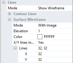
A wire frame can be shown combined with or instead of the rendered image. The number of lines in the wire frame can be set individually for the x and y directions.
To assure that all parts of the wire frame are visible when combined with a solid image it can be elevated or lowered relative to the rendered image.
The wire frame colors can be set to adopt the current color scale (Var color) otherwise a fixed color can be defined.
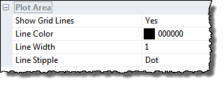
The Plot Area controls the appearance of the grid lines, which are lines setup to follow the z-tick marks in the two most distant edges.