For tube scanners hysteresis is a common problem. To handle this specific distortion SPIP has a built in algorithm for correcting worst part of the hysteresis by modeling the hysteresis curves for the X and Y axis independently by 2nd order polynomial functions. The hysteresis model is tuned such that the Fourier peaks in the corrected image are maximized.
The hysteresis correction is performed by clicking on the XY Hysteresis button found in the Modify tab group > Scaling and Correction panel.![]()
You can try the method on the hyst.bcr file which came with SPIP.
![]() Open hyst.bcr.
Open hyst.bcr.
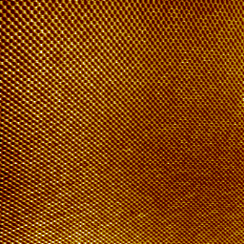
You will find that the repeat distance for the features is highest on the upper left part and smallest on the lower right part. This is an effect of non-uniform scanning caused by hysteresis. The scanner has sampled at equal time intervals but the scanning speed was lower on the upper left part where the scan started than the lower right part.
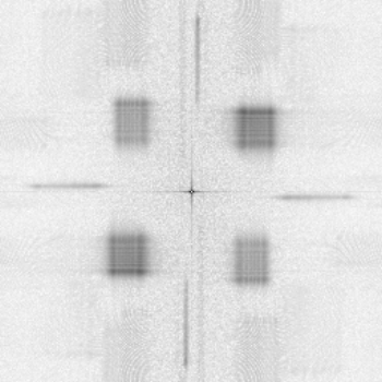
![]() Take a look on the Fourier image and you will see that the narrow peaks typical of calibration objects have broadened to rectangular forms:
Take a look on the Fourier image and you will see that the narrow peaks typical of calibration objects have broadened to rectangular forms:
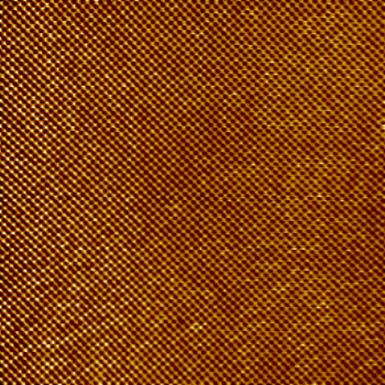
![]() Click on the XY Hysteresis button and a new corrected image will be calculated:
Click on the XY Hysteresis button and a new corrected image will be calculated:
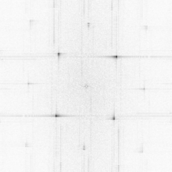
![]() Make a new Fourier image and you will see that the Fourier peaks associated with the real structure have been restored
Make a new Fourier image and you will see that the Fourier peaks associated with the real structure have been restored