By use of the Selective filtering menu the user can interactively remove selected Fourier components. This may be useful for creating a nicer image, enhancing structures or assisting the unit cell detection
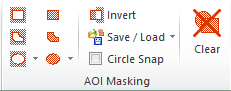
The Fourier components/pixels to be removed can be selected by the AOI Masking tools found in the FFT Image Tools tab set:
The left AOI marking tools are used for defining their interior as belonging to the AOI and to be preserved when performing an inverse FFT filter. Their counter parts to the right will define their interior as being excluded from the AOI and to be rejected in an inverse FFT filter process.


In contrast to spatial images there are two ellipses tool pairs, one which is marked in the same way as the image ellipsis tool and another that will keep the center at the origin of the FFT image. The latter is useful for performing "free hand" band filtering. Both ellipses tools will be maintained in a circular form when the keyboard Shift key is pressed.
Both Ellipses tool has an optional Circle Snap function, set from the same panel. This function caused the program to find the highest peak inside the ellipses area and adjust its position so that its center equals the peak position. This is for example valuable for rejection of noise artifacts at certain frequencies.
Below is seen an example on an Inverse FFT Filtering result using a Ellipsis in exclude mode to reject the lower frequencies and an ellipsis tool to reject the higher frequencies. Both ellipsis are circular and centered at the FFT origin.
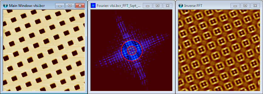
FFT Filter bandpass example using tool AOI Ellipses tool
The following shows an example of including only some Fourier components by use of the polygon AOI marker tool.
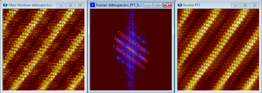
The main window most left, holds a repetitive structure and has also a specific orientation. The effect of this can be seen in the full Fourier transform where the highest peaks form lines, oriented perpendicular to the spatial line structures. It is possible remove all Fourier components not associated with the lattice structure using the polygon AOI tool to mark the relevant lattice peaks. The filtered result created by the Inverse Fourier function provides a better impression of the repetitive features of the image.

Fourier Amplitude Threshold control
The Color Scale clip markers of the Fourier image is synchronized with the Min and Max scroll bars of the Fourier Dialog. The min and max values are used to define Fourier components to be removed based on their magnitude. Components having values lower than the min value or higher than the max value will be set to zero.
When clicking on the Inverse FFT button the filtered image will be shown. Note that it is not necessary to perform and inverse FFT if you want to detect unit cells without the excluded Fourier pixels. Checking the "Auto Inverse" will cause a computation of the filtered result while changing the threshold values.
When the Min threshold value is set low it will mainly affect the white noise and you may regard the technique as a white noise filter. The scaling defined in the Output tab will change the sensitivity of this function. If the Min threshold is set high then only the most prominent Fourier components will be appear in the filter result image. This is demonstrated in the following example.
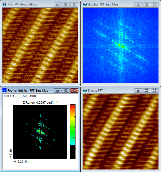
Fourier Amplitude Threshold Filtering Example.