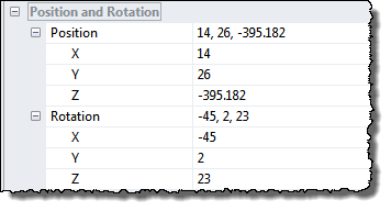
By use of the Position & Rotation it is possible to control the position, scaling and rotation angles of the surface.
The position and rotation of the surface can also be controlled interactively by the mouse and arrow keys as described in the Navigation Controls section.
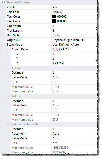
The X-Y-Z axes can be displayed with a large set of optional parameters such as font, axes tick marks and scaling. Below is the most important, and may be not so obvious, parameters described.
This option allows you to define the lower left corner of the image as the origin of the coordinate system independent of the offset property of the image.
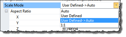
There are three scaling modes defining how the z-values are scaled:
The XYZ Scale factors determine the geometric shape of the surface.
The most important is the Z-scale factor, which scales the height values of the image and can be controlled by Mouse Y-movement when in the Scale navigation control mode or in any mode by combining the z key with mouse movements.
For surface structures with large corrugations it can be an advantage to show the image in the 1:1 Aspect ratio as this gives the best geometrical feeling. This is especially true for images used for tip characterization.
For direct comparison of images it might be useful to define fixed min and max values for the Z axis.
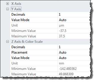
The settings for the three axes are very alike; the only difference is that the Z Axis has an extra Placement parameter.
Determines the number of decimals used for the tick values on the axes.
This parameter determines if the z-axis shall be visible and if so in which image corner it should be shown.
The following four value modes are selectable: