
All SPIP 2D images can be visualized in 3D by clicking on the 3D-tool in the Image Ribbons General tab or just the numerical '3' on the key board. This will create the 3D Window showing the image in 3D perspective.
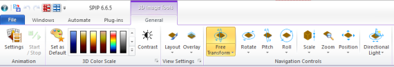
The 3D Animation Pane is activated by clicking the Settings button. The Start/Stop button can be used as an alternative to the buttons in the 3D Animation pane, which is the place to design a 3D animation of a surface.
You can select a color scale in the same way as for 2D images. Contrast and brightness can be set from a mini dialog pop-up by clicking the Contrast button. For 3D images you will often want to use a very low contrast in order to give the surface a softer look.
For setting a very low contrast it can be necessary to use the Color Scale Editor and set the contrast markers outside the visible color scale range. By clicking the Default button you can define any of the built in color scales or a scale of your own design as the default.
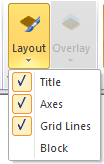
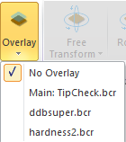
In the View Settings Panel you can switch Title, Axes and Grid Lines On/Off. Furthermore, you can define an overlay Image different from the 3D image itself for defining the colors. This may be very useful if you have an AFM topographic image acquired together with a phase image and want to combine the two images by using the colors from the phase image overlaid on the topographic image. There is an 3D overlay example show in the description of the "Surface Coloring and Overlay" section of the View Settings Pane.

|
|
|
The Navigation Controls Panel provides easy access to various 3D rendering parameters that determines how the 3D image will appear. You can use the mouse or arrow keys to control the parameters associated with the selected navigation control.
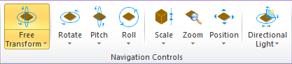
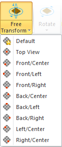
The default mode is the Free Transform, where you both can rotate the surface around the z-axis and change the pitch.
The z-rotation axis and the pitch rotation axis will be indicated as shown below and the mouse cursor will reflect the Free Transform mode. After you have familiarized yourself with the 3D navigation tools you may turn off the navigation indicators by clicking the button in the upper right corner of the 3D window. While moving the mouse up/down the image will rotate around the pitch axes and when moving the mouse left/right it will rotate around the z-axis. For fine adjustment you may also use the keyboard arrow buttons.
![]()
Furthermore, the pull down menu contains a number of preset combinations of rotation and pitch, which brings the 3D image in a well defined rotation angle and pitch. The Default menu button recalls the relevant parameters from the default view settings file, which can be defined in the View Settings pane, this includes also the x,y position and the zoom factor.
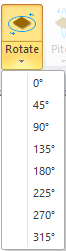
When selecting the Rotate mode the 3D image will rotate around the z-axis by dragging the mouse horizontally without altering the pitch. You can also select one of the preselected rotation angles. I
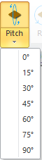
In the Pitch mode the image is rotated around a horizontal pitch axis by dragging the mouse vertically. You may also chose one of the predefined pitch angles.
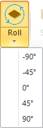
In the Roll mode the image is rotated around an axis, associated with the z-axis and pointing into the plane, by dragging the mouse horizontally or using the left/right keyboard arrow keys. Here again you can choose among predefined angles from the pull down menu.
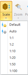
The Scale mode makes it possible to amplify or weaken the z values of the image, making it easier to inspect smaller details. This is done by dragging the mouse vertically or by use of the up/down arrow keys. You may also choose one of the predefined scale factors or select Auto. The Auto scaling will adopt the image z-range and in most cases provide a good result.
In the Zoom mode you can zoom in and out by dragging the mouse vertically or by use of the up/down arrow keys. You may also prefer just to use the mouse scroll key, which is available in all modes.
By clicking the Fit key in the pull down menu the zoom level is set such that the entire image gets visible and makes the best use of the window area.

The Position mode allows you to position the image in the window by dragging the mouse vertically and horizontally or by use of the arrow keys on the keyboard. The Center button on the pull down menu will position the center of the image in the center of the window.

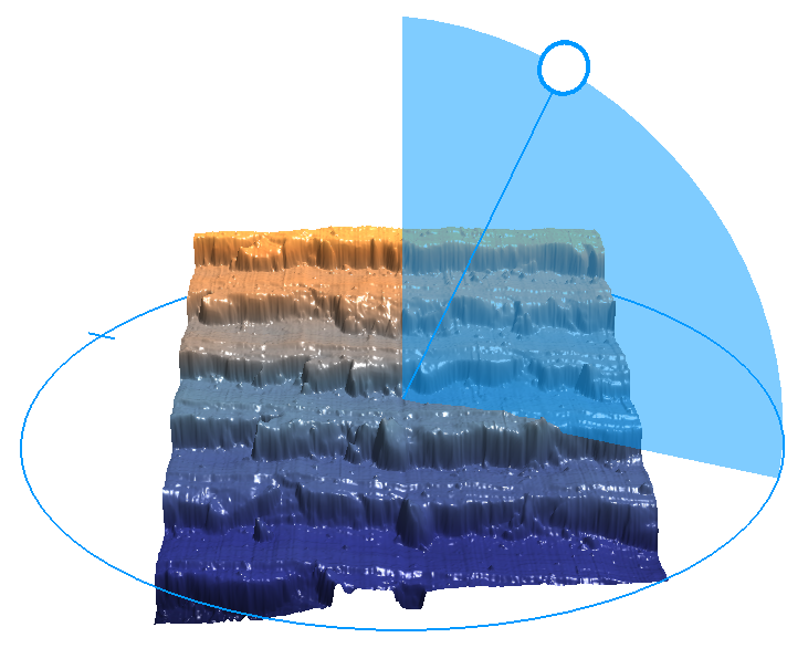
In the Directional Light mode you can control the position of the light sources by their angle around the image z-axis and elevation. Dragging the mouse horizontally will change the angle while dragging vertically will change the elevation. The light source position and direction will be indicated as shown below.
By default light source number 1 will be the active one but by pressing down the numeric keys '2' to '8' while dragging the mouse, the position of the associated light source will be modified.
Each of the light sources can easily be turned on/off by the numeric keys '1' to '8'. The '0' key will turn all lights off and bring the window in to a normal color mode where the selected Color Scale defines the colors. In most cases it will be desirable to use at least one light source to visualize the finer details.
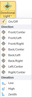
The predefined light positions are all dedicated to light source '1'.
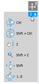
Independent on the selected 3D control mode you can apply short cut key combination for altering a specific 3D view parameter. The available short cut keys are displayed
in the top right part of the 3D window together with their associated icons as shown below. This info window can be turned off by clicking on the 'i' button at its upper right corner. Likewise, you may turn off the navigation indicators by clicking the button above.
| Mode | Icon | Shortcut key |
|---|---|---|
|
(Pitch & Rotate) |
|
Ctrl |

|
Shift + Ctrl | |

|
Z | |

|
Shift + Z | |

|
Shift | |

|
1..8 |
The View Settings of the 3D Image window enables you define more 3D display parameters by numerical values. The menu contains a number of sub-menus, which can be opened or closed by clicking on the associated buttons. Below is seen the menu in its most compact form:
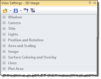
As seen above the 3D View Settings contains 10 groups, which controls the following functions:
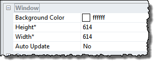
| Window | Defines the background color and the window size |
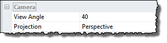
| Camera | Defines the View Angle |
| Title | Defines the Title appearance |
| Lights | Controls emulated light sources illuminating the surface |
| Position and Rotation | Controls the position, and rotation angle of the surface |
| Axes and Scaling | Defines the appearance of axes and scaling of the surface image |
| Image | Defines coloring of the surface, handling of void pixels, block mode |
| Surface Coloring and Overlay | Defines the coloring and possible overlay image |
| Surface Wire frame | Defines optional wire frame settings |
| Plot Area | Defines the grid lines connected to the axes |
In the Window section you can define the background color, the size of the window and set it to be updated automatically whenever the source 2D window is modified. The Auto Update function is a strong feature for following changes in the connected 2D image which are difficult to visualize in the 2D image window.
The camera section allows you to define the projection and the view angle.
Projection
The projection mode can either be perspective or orthographic. In the perspective mode the most distant structures will appear smaller on the screen while in orthographic mode all structures will keep their size as when seen in 2D.
The view angle takes care of the angle by which the object is viewed and corresponds to changing the lens of a camera.
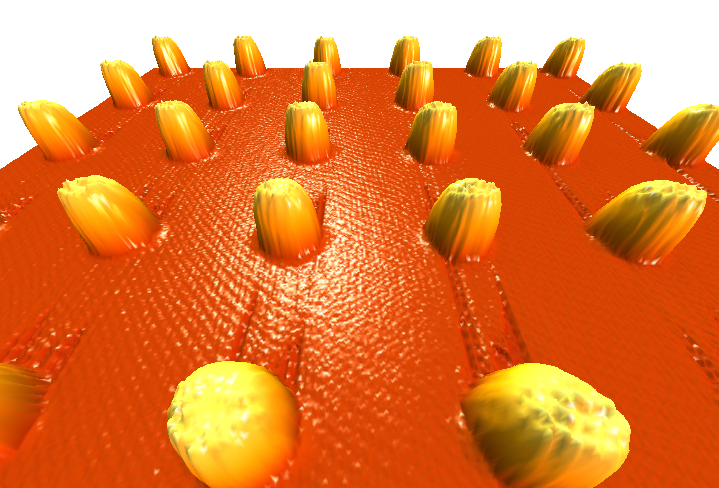
The default View Angle is 40 degrees as shown in the example below:
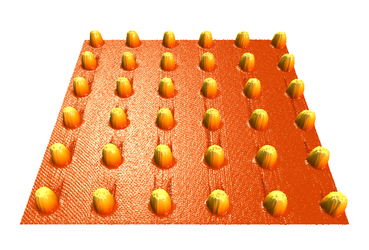
Enlarging the view angle corresponds to a change the lens of a camera to a wide angle lens. It will appear as if the surface is further away and you might want to bring it closer again by changing the Z-position coordinate. The net result will show the individual features with a larger perspective distortion, below is used a view angle of 80 degrees:
To identify the image a title can be written with an optional font style. The title text can adopt the file name of the images or be to an entered text.
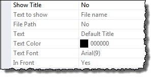
By selecting Yes for In Front the title will always be shown in front of the image.