This is a way dividing the image into up to three types of Shapes. The method uses the principle of watershed segmentation applied to the slope (or differential) image of the Detection Image. The slope image is equivalent to the Gradient Norm of the Detection Image. Watersheds (ridges) in the slope image corresponds to regions of maximal slope in the Detection image, e.g. at the border of Particles of Pores. As the water basins are found in the Slope Image the type (Particle, Pore or Plateau) has to be evaluated afterwards using the Detection Image as described below.
Check this on in order to detect Particles. In this Detection Method Particles are defined as Shapes with a Plateau Index larger than the Plateau Range value (which is zero by default). Put in other words: If most of the Shape's interior is higher than the mean height at its periphery it will be categorized as a Particle – in this context “most” is the fraction given by the Plateau Range value. See also Plateau Range below.
Check this on in order to detect Pores. In this Detection Method Pores are defined as Shapes with a Plateau Index less than minus the Plateau Range value (which is zero by default). I.e. if most of the Shape's interior is lower than the mean height at its periphery it will be categorized as a Pore – in this context “most” is the fraction given by the Plateau Range value. See also Plateau Range below.
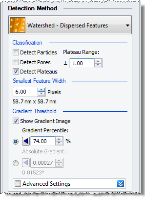
Check this on in order to detect Plateaus. Plateaus are defined as Shapes with a Plateau Index (see definition for Plateau Index) inside the Plateau Range. When the Plateau Range is +/- 0.00 no Shapes will become Plateaus. See also Plateau Range below.
If the features in the image are part Particle and part Pore (high/low or bright and dark), then a good trick is to detect Plateaus only, and set the Plateau Range all the way up to 1. In this case it will often be a good idea to uncheck “Include Shapes on Borders” on the Post Processing tab, as background might otherwise be reported as one big Plateau.
The Plateau Range is +/- the value entered and specifies the Plateau Index range for which Shapes in the Detection Method are categorized as Plateaus. In short the Plateau Index is the ratio between the sum of Z values inside the Shape and the sum of the absolute values of the same Z values, all Z-values calculated relative to the mean Z-value of the Shape's Contour. See also Detect Particles / Pores /Plateaus above. If only Particles or Pores or Plateaus have been selected this value will have the same effect as using the Plateau Index as a Parameter Filter during Post Processing. Be careful with changing this value away from its default value (zero) , since left at a high value it may disturb the analysis of subsequent images.
Before calculating the gradient image used for the detection (or segmentation) step the Detection Image is smoothed. This is done in order to avoid over-segmentation caused by noise resulting in too many too small Shapes. This value specifies the cut-off wavelength of the Gaussian envelope used for the smoothing. If the image is completely free from noise this value can be set to zero. But in most real life situations this value should be set to approximately the lateral size in units of pixels of the smallest feature you expect to detect; sometimes a bit smaller. As a help SPIP™ will show the dimensions of the pixel number entered in metric units just below the edit box. See the Best Practice guide for further help.
In order to further avoid over segmentation the Gradient Image is thresholded before being segmented by the watershed algorithm. By default the threshold level is given as a 50% percentile of the distribution of gradients.
Toggle this option to see the Gradient Image used for the segmentation. In this image the effect of the smoothing described previously can be seen. The specified Gradient Threshold is indicated by the lower Color Clip Marker and the Color Clip Overlay in the Gradient Image. The Gradient Image will update when the Smallest Feature Width number is changed. For topographic images the Gradient Image will give the actual slopes everywhere in the smoothed Detection Image. For other image types the Gradient Image may not have an obvious physical meaning.
The Gradient Image is automatically thresholded in order to avoid the detection of features surrounded by small slope maxima. This means that a noisy or wavy background will be ignored by the Detection algorithm.
Having the threshold value as a Percentile value makes the method robust. Therefore this is the default setting. Decrease or increase this number in steps of 5 or 10% in order to enhance / reduce the sensitivity of the Detection. Often when images contain dominating slopes (e.g. steps) much higher than those surrounding the features of interest it is necessary to lower this value considerably.
For processing a batch of images which have been recorded under the same conditions, it is advantageous to enter the Gradient Threshold as an absolute value. This will give consistent results whereas the Percentile method will generate slightly different threshold values depending on the sizes and number of particles in different images.
For topographic images (when the x, y, and z axes are all in length units) the Gradient Image is an image of surface slopes. In such cases it can make a lot of sense to specify an absolute slope threshold. An Absolute Gradient of unity will correspond to slope angles of 45 degrees. Usually surface slopes are much smaller than this, though.