The Measure Shape tools allow the user to make a wide range of measurements interactively by drawing the available Shapes in an image. The results are shown in a spreadsheet like pane (the Shape Measurements pane) in histograms, in scatter plots or directly in the image. The visual appearance of Shapes in the image window is controlled in View Settings.
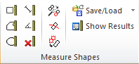
The available Shapes and related tools, which can be accessed from the Measure Shapes panel of the General ribbon tab:
 This tool is primarily used for measuring lateral dimensions, height, area and volume(s). The shape is simply drawn by defining one corner by clicking the mouse down while the opposite corner is defined on the mouse release.

This tool used for measuring distances between selected points l (Length). After having selected this tool click and hold down the left mouse button inside the image and drag the mouse until the line has the desired length and orientation and then release the mouse button.

This tool is primarily used for measuring lateral dimensions, height, area and volume(s). After having selected this tool click the left mouse button inside the image to set the first point on the Polygon Shape's contour. Add contour points by moving the mouse and left-click. In order to close the polygon the right mouse button is pushed. It is also possible to “freehand” draw a Polygon Shape by holding down the left mouse button while moving the mouse.

This tool is primarily used for measuring diameter, area, and volume(s). After having selected this tool click and hold down the left mouse button inside the image and drag the mouse until the ellipse has the desired size and proportions and then release the mouse button. To draw a circle, keep the Shift key down while dragging the mouse.

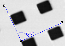
Use this tool for measuring angles. You can draw one of the angle lines with the mouse and when releasing the left mouse button the other angle line will appear with the same length but with a 90 degree angle. The Angle shape can thereafter be repositioned and the angle shape changed.

This tool deletes all Shapes from the image. This is often used in conjunction with the Particle & Pore Analysis module to clear the image. This function is also available in the context menu (right mouse click) for the Shapes in the image.

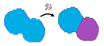
SPIP™ can split selected Polygon Shapes automatically. The polygons will be split at any significant waists of the shape. Select one or more Shapes and click the tool to split them. This is almost solely used in conjunction with the Particle & Pore Analysis module.

Push this tool key and draw a line through a Polygon Shape (end line with mouse right-click) in order to split the Shape. This is almost solely used in conjunction with the Particle & Pore Analysis module.

Select two adjoining (connected or overlapping) Shapes in the image and push this tool key to have them merged. This is almost solely used in conjunction with the Particle & Pore Analysis module.

All Measure Shapes in the selected image can be saved as a group and reloaded again on the same or on another image. This functionality used for:
• Exporting Shapes for further customized analysis in e.g. MATLAB
• Importing Shapes which have been processed in e.g. MATLAB
• Saving the result of a successful Particle&Pore Detection to be used in a later SPIP™ session
• Re-use of (manually created) Shapes on several images, for example in combination with Batch Processing

Forces the display of the Shape Measurements pane where all calculated parameters, statistics and summary information are displayed.
Note: Drawing and splitting continues until the active tool is de-activated, either by clicking the tool key again, by selecting another tool or by clicking the white arrow marker tool ![]()
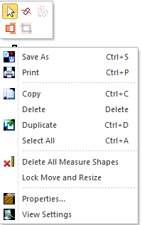
By right clicking on an active measure shape its context menu will appear and provide easy access to common operations.
An active (selected) Shape can conveniently be duplicated by pressing Ctrl+D
For automatic image analysis the Particle & Pore Analysis module (requires license) is used for feature detection and automatic generation of Polygon Shapes. The Particle & Pore Analysis tool key is found in the Feature Analysis pane of the Analysis ribbon tab.
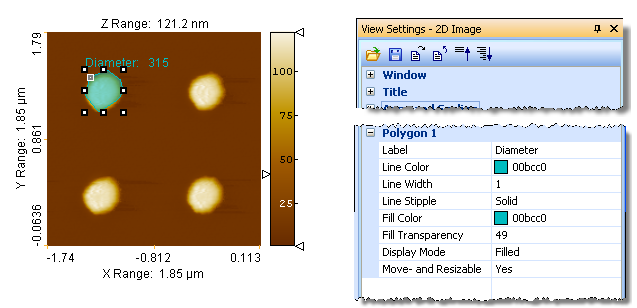
Various display options can be set for one or more selected Shapes in the 2D Image View Settings such as color, fill-transparency etc. This includes the possibility for displaying a label next to each Shape which is the value (in units of nm) of any chosen calculated parameter. The label may just be the ID number of the Shape.
Shapes can be selected, split (polygon Shapes only), merged, deleted, moved, and resized interactively.
Select a Shape by clicking (left mouse click) on the Shape's border, or clicking inside the Shape while pressing the shift key. Shapes can be multi selected by holding down the Ctrl key. It is also possible to select all Shapes within a rectangular area by pushing and holding down the left mouse button while dragging the mouse. In order to select all Shapes right click the image and choose Select All from the context menu or type <Ctrl>+A. Every time one or more Shapes are selected in the image, the corresponding rows in the Shape Measurements pane (when present) will highlight, and vice versa.
In order to prevent the user from un-intentionally moving or resizing Shapes there is a possibility to lock (and unlock) the Shapes for moving and resizing. This option is available in View Settings as well as in the context menu (right mouse click) of a selected Shape.
All Shapes generated by the Particle & Pore Analysis module are by default locked meaning that they can be selected, deleted merged and split, but not resized or moved until unlocked.