The lateral calibration depends on images containing structures with known pitch dimensions.
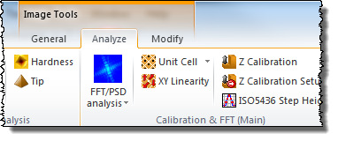
The process is started by clicking on the key for Unit cell detection, ![]() . which is found in the Analyze > Calibration & FFT panel. There are two optional Unit Cell detection methods a "High Accuracy" and a "Fast", the latter should only be used if you just are interested in a quick estimate. If you are not sure about the linearity of the image you should rather use the XY Linearity Analysis activated by a button found in the same pane.The "high accuracy" method makes use of a special iterative sub pixel Fourier Peak determination algorithm. More information on the unit cell detection mathematics is given in the section Detection Unit Cells of the Reference Guide.
. which is found in the Analyze > Calibration & FFT panel. There are two optional Unit Cell detection methods a "High Accuracy" and a "Fast", the latter should only be used if you just are interested in a quick estimate. If you are not sure about the linearity of the image you should rather use the XY Linearity Analysis activated by a button found in the same pane.The "high accuracy" method makes use of a special iterative sub pixel Fourier Peak determination algorithm. More information on the unit cell detection mathematics is given in the section Detection Unit Cells of the Reference Guide.

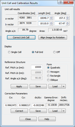
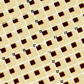
The Unit Cell detection will automatically give you the necessary information about the unit cell, and correction factors shown in the Unit Cell and Calibration Results dialog and the lattice structure will also be drawn in the spatial image as shown below.


The Unit Cell Results are shown in the top section with its vector coordinates and extracted length and angles. Likewise is the angle between the unit cell vectors shown together with the inner area of the Unit Cell.
You can control how to display the unit cell result in the spatial image: as a Single Cell, Full Grid (as shown above) or Off.
You may use the shown Correction Parameters to correct the Unit Cell vectors by clicking this button.
It is often useful to rotate an image so that the unit cell or line structure is parallel to the axes, - this can be done automatically by clicking on the Align Image by Rotation, see more details about image rotation in the Rotation section.
You can enter the proper reference values for the reference unit cell, the length of the two unit cell vectors and their angle.
The correction parameters can be calculated based on three unit cell forms: Quadratic, Hexagonal, Rectangular or the generic Oblique form.
The reference data can be saved into individual files and recalled again. Note that the reference files *.crp may also contain step height information, which is preserved when saving the lateral reference data.
Click on the Apply button to get the corresponding correction factors calculated.
The three correction parameters Cx, Cy, dx/dy are the necessary parameters for reconstructing an image with correct scaling and angles. They are described more detailed in the Reference Guide Lateral Calibration by Quadratic Unit Cells. Briefly the Cx and and Cy tells how much to stretch the image in the x and y directions to get the dimensions correct. The dx/dy parameter tells how much the image is skewed. The Gamma Error is another way of expressing the skewness and tells how much the x,y axes angle differs from orthogonality. The Drift parameter tells how much the image is drifting in the x-direction when assuming that the Gamma Error is solely caused by drift and not by coupling between the x,y scanners. Note, that the drift parameter has only meaning for images that have been raster scanned and where the scanning speed is known. For ideal images the Cx, Cy and dx,dy parameters should be 1.0, 1.0, 0.0 respectively.
The calculated correction parameters can be saved and recalled so that they can be applied to other images. To enter correction parameters manually you can open the dialog from the menu bar: Processing®XY-Calibration
To perform a correction by the calculated correction parameters or some entered parameters by you, click on Correct.
If the correction parameters were the one calculated from the current image, you can check the correction, by performing a new Unit Cell detection:
A new calculation of the correction parameters should result in values close to neutral, i.e., xc =1, yc =1, and dx/dy = 0.